RC Car Control via PC using XBee and Processing
This tutorial will show you how you can convert an old (or new) Radio Controlled car, in order to control it via the PC. Of course a laptop is preferable for controlling the car outdoors. Let's get it started!
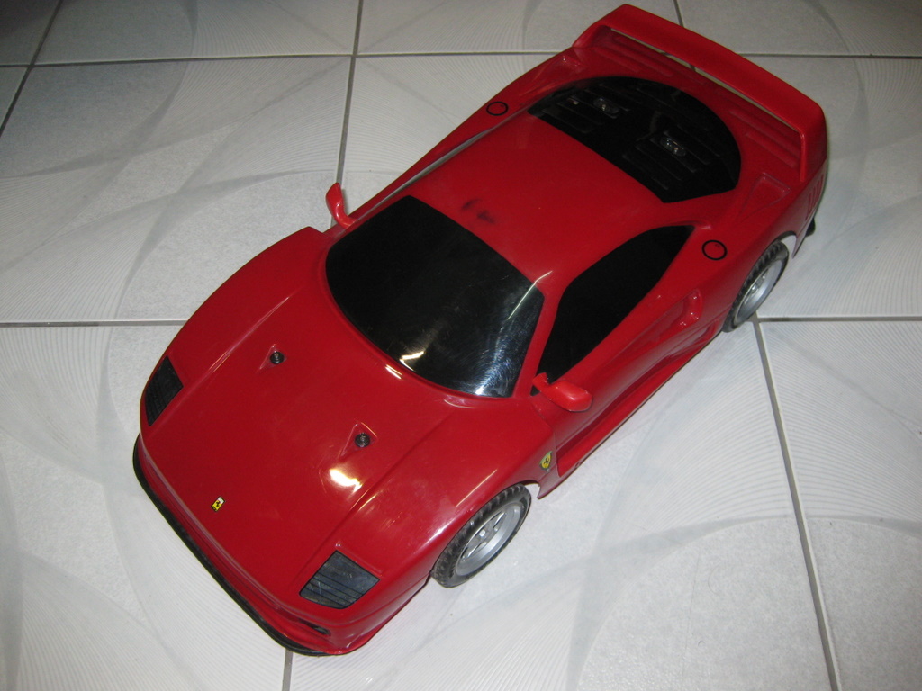
This F40 is actually very slow! It has 2 motors. One is used for forward and reverse and the other for steering. Newer RC cars use a servo for steering. In this case, you will need a motor controller that has also the option for connecting a servo. A useful web store is Pololu Robotics which has a variety of motor controllers.
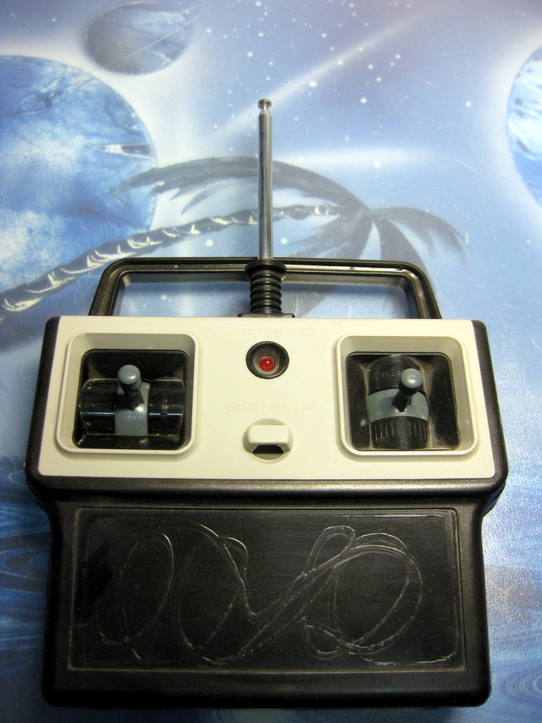
This is the old transmitter but still operational.
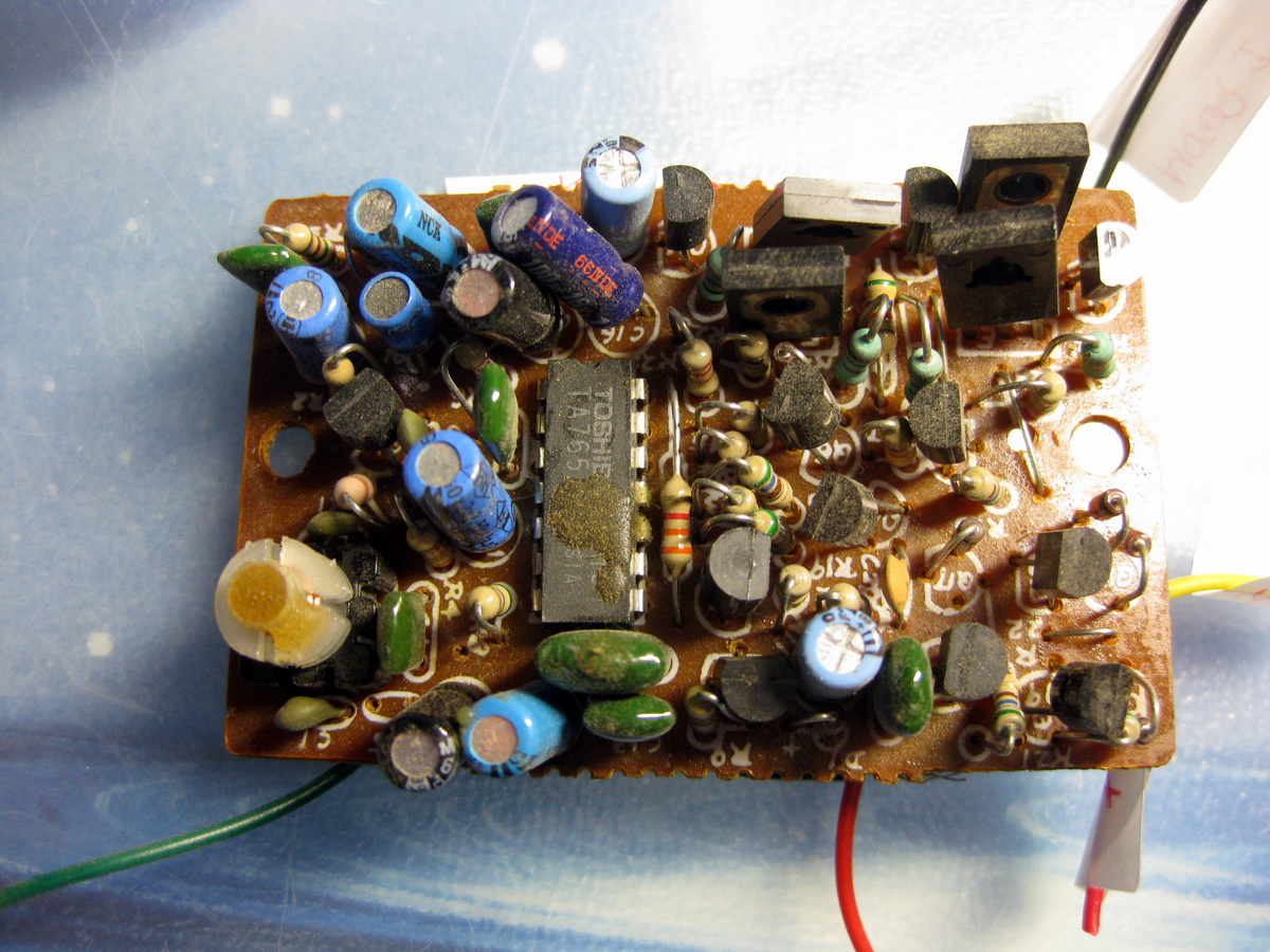
This is the old receiver which is also operational.
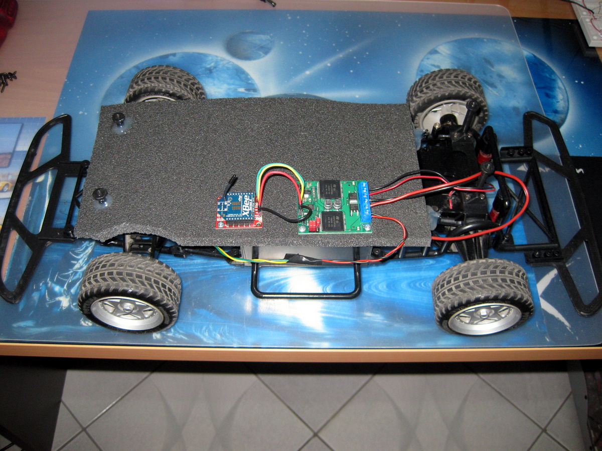
The old RC car after the modification. You can see the motor controller at the right and the XBee module (attached to the XBee Explorer regulated) at the left.
For this project you will need:
Hardware:
1 motor controller. I used a Qik Dual Serial Motor Controller but any other motor controller that accepts TTL (Transistor Transistor Logic) commands will do fine also. If your RC car has a servo for steering you need to find a suitable motor controller that accepts a servo connection. When buying a motor controller make sure that the motor controller is able to handle the current (Ampere) output of the motors.
2 XBee 2.4GHz modules. I used two XBee 2.5 Series.
1 XBee Explorer regulated. This board will have attached the XBee that will be on the car-side.
1 XBee Explorer USB. This board will have attached the XBee that will be on the PC-side.
1 XBee Explorer Serial from Sparkfun too. This board is useful for updating the firmware of the XBees and setting configuration parameters so as to create the wireless link.
Software:
How to configure the wireless link between the two XBees:
For establishing a wireless link between the two XBee modules first you must set the correct parameters for each one. I used the information on this link for configuring the two modules.
Connecting the components together:
Let's start by connecting the motors to the motor controller. This link will help you in the process ...
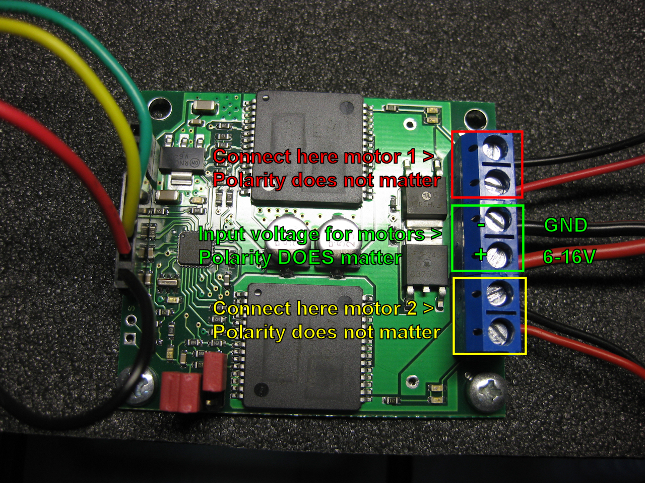
As you see, connecting the motors is a simple task. Motor 1 (channel 0) handles forward and reverse whereas motor 2 (channel 1) handles the steering. You only need to pay attention to the polarity of the power supply (in that case the batteries of the RC car) for the motors. The input voltage must be between 6 to 16 volts. You can check with a multimeter how much voltage the batteries supply.
Let's connect now the XBee Explorer regulated to the motor controller.
Let's connect now the XBee Explorer regulated to the motor controller.
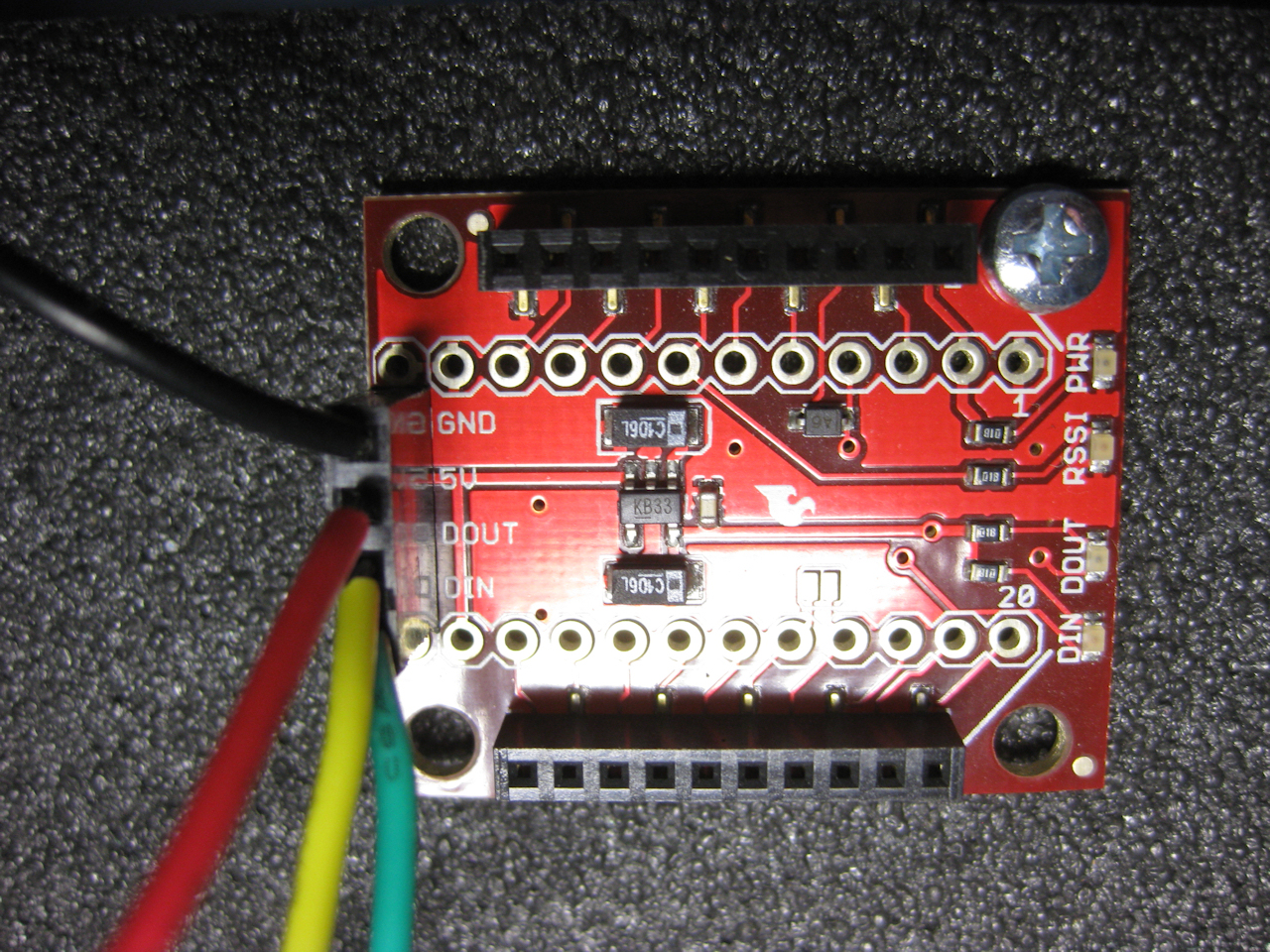
In the above picture notice the connections labeled: GND, 5V, DOUT, DIN. Now, this picture will help you a lot! The objective here is to make the following connections from the XBee Explorer to the motor controller:
XBee > Motor Controller
XBee > Motor Controller
------------------------------
GND > GND
5V > 5V (regulator output)
DOUT > RX (TTL serial input)
DIN > TX (TTL serial output) This connection basically is not needed as we will not read anything from the motor controller. You can leave it disconnected.
After you have made the connections, insert the XBee module into the Explorer regulated and you have almost completed the hardware part! Picture below shows an overall view of the connected components.
After you have made the connections, insert the XBee module into the Explorer regulated and you have almost completed the hardware part! Picture below shows an overall view of the connected components.
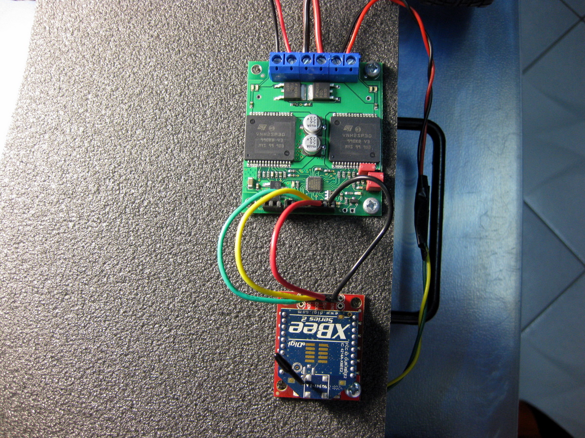
Before proceeding to the next step, power up the RC car (via its switch) and notice the blinking rate of the green status led of the motor controller. This is important as the status led shows whether the motor controller's TTL port is connected to the XBee's TTL port. In normal operation the green led must blink every 1.3 seconds according to the data sheet.
In my case, the XBee communicates with the motor controller at 9600 bps (baud rate). The baud rate of the XBee has been set (at 9600 bps) using the X-CTU software. The baud rate of the motor controller is set via the three jumpers. As it is shown in the picture above jumpers 1 and 2 are shorted so as to enable the 9600 bps baud rate on the motor controller. This information can be found in the data sheet of the motor controller.
The next step is to connect the XBee Explorer USB (with the attached XBee) to your computer. If the Wizard asks for drivers, then download the FTDI drivers from the FTDI website or inside the Arduino editor zip file (under the "drivers" folder). Below you can see the other XBee connected to the PC.
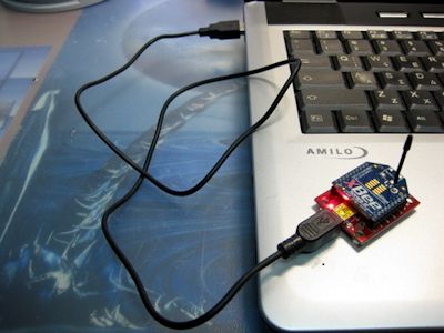
Now, go to Device Manager and notice that a new COM port has appeared under "Ports (COM & LPT)". If you have many COM ports this may be difficult to notice, so disconnect the XBee Explorer USB, notice the existing port numbers and then reconnect the XBee Explorer USB.
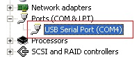
In my case, the XBee module is accessible via ComPort 4. In your case, this number may be different. Now that we know the ComPort number let's move on to the Processing code.
The Processing code:
Below is the full Processing code. Copy and paste it into an empty Processing sketch.
/*

 This sketch reads user input from the keyboard and sends data
 to the selected COM port so as to control the RC car.

 Version 1.0
 Code licensed under Creative Commons Attribution-ShareAlike 3.0 License
 https://creativecommons.org/licenses/by-sa/3.0/

 by John Tompros (2009)

 https://sites.google.com/site/electronicprojectsprogramming

 Motor for forward and reverse is connected to channel 0
 Motor for left and right is connected to channel 1

 */

import processing.serial.*;  //Required library

Serial comPort;           //Create a serial port object
int speedForward = 0;     //Integer to hold the forward speed rate. Set initial forward speed rate
int speedReverse = 0;     //Integer to hold the reverse speed rate. Set initial reverse speed rate

void setup()  //Runs once
{
  size(400, 400); //Just for showing the window
  background(0);  //Set background color

  println(Serial.list());  //Notice how your com port is listed

  //Select serial port for communication. You must change the number inside [] to correspond to your correct com port of your pc
  //in my case, com port 4 is assigned the number 1
  comPort = new Serial(this, Serial.list()[1], 9600);
}

void draw() {                        //This is the main loop
  if(keyPressed == true) {           //Checks to see if a keyboard key has been pressed. Returns true if a key has been pressed
    if (key == 'e' || key == 'E') {  //Set forward key
      delay(10);
      speedForward ++;    //Increase forward speed as long as the key is pressed
      comPort.write(136); //Send command to the motor controller to start the motor (in forward) connected to channel 0
                          //This information is found in the datasheet of the motor controller
      comPort.write(speedForward); //Send current motor speed
      //println(speedForward);
    }
    else if (key == 'c' || key == 'C'){  //Set key to reduce speed and to stop the motor eventually
      if(speedForward <= 5){  //Minimum motor speed threshold, to avoid negative numbers to be passed as commands to the motor controller
        comPort.write(134);   //Send command to the motor controller to stop the motor connected to channel 0
        comPort.write(60);    //Apply partial brakes
        delay(300);
        comPort.write(134);   //Send command to the motor controller to stop the motor connected to channel 0
        comPort.write(127);   //Apply full brakes
        speedForward = 0;     //Reset forward speed
        speedReverse = 0;     //Reset reverse speed
      }
      else{
        speedForward --;              //Else reduce forward speed
        comPort.write(136);           //Send command to the motor controller to apply current speed to the motor connected to channel 0
        comPort.write(speedForward);  //Send current reduced motor speed
        //println(speedForward);
      }
    }
    else if(key == 'x' || key == 'X'){  //This key is assigned to the brakes
      comPort.write(134);               //Send command to the motor controller to stop the motor connected to channel 0
      comPort.write(60);                //Apply partial brakes
      delay(300);
      comPort.write(134);               //Send command to the motor controller to stop the motor connected to channel 0
      comPort.write(127);               //Apply full brakes
      speedForward = 0;                 //Reset forward speed
      speedReverse = 0;                 //Reset reverse speed
    }
    else if(key == 'q' || key == 'Q'){  //This key is assigned to reverse
      delay(10);
      speedReverse ++;                  //Increase reverse speed as long as the key is pressed
      comPort.write(138);               //Send command to the motor controller to start the motor (in reverse) connected to channel 0
      comPort.write(speedReverse);      //Send current reverse motor speed
      speedForward = 0;                 //Reset forward speed
    }
    else if(key == CODED){
      if(keyCode == LEFT){   //Set key for left steering

        //Send command to the motor controller to start the motor (in forward) connected to channel 1
        //that is the channel where the motor responsible for the steering is connected to
        comPort.write(140);

        //Send a value to start the steering motor
        comPort.write(45);
      }
      else if(keyCode == RIGHT){  //Set key for right steering

        //Send command to the motor controller to start the motor (in reverse) connected to channel 1
        //that is the channel where the motor responsible for the steering is connected to
        comPort.write(142);

        //Send a value to start the steering motor in the opposite direction
        comPort.write(45);
      }
      else if(keyCode == UP || keyCode == DOWN){  //Set keys for returning the steering to the center
        comPort.write(135);                       //Send command to the motor controller to stop the steering motor
        comPort.write(0);                         //Send the stop value
      }
    }
  }
  if(speedForward >= 110){  //Set a speed limit
    comPort.write(134);     //Send command to the motor controller to stop the motor connected to channel 0
    comPort.write(60);      //Apply partial brakes
    delay(300);
    comPort.write(134);     //Send command to the motor controller to stop the motor connected to channel 0
    comPort.write(127);     //Apply full brakes
    speedForward = 0;       //Reset forward speed
    speedReverse = 0;       //Reset reverse speed
  }
}
Running the sketch:
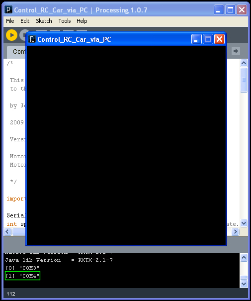
By running the sketch you will presented with a black window. This is normal! In the output section of Processing you must take notice of the number inside the brackets that correspond to your ComPort number that you found out earlier. The number inside the brackets must be the same in the following statement in the processing code:
comPort = new Serial(this, Serial.list()[1], 9600);In my case, this number is the "1". In your case the number may be different.
When the sketch is running the user can control the car with the following keys:
"e" for forward and increasing speed
"c" for braking and reducing speed
"x" for instant braking
"q" for reverse
"left" key for turning left
"right" key for turning right
"up" and "down" keys for centering the steering
Of course, if you like you can change the code so as other keys can be used.
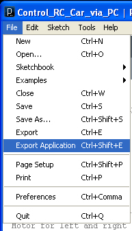
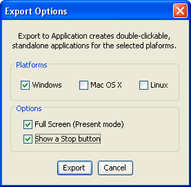
Exporting the sketch:
Processing has also an option for exporting the sketch to run as a stand alone .exe application.

That's the end of that project! I hope you liked it and learned something new along the way!